Sale is ON! Save Big on Bundles!
Sale is ON! Save Big on Bundles!
Welcome To SoloStrength Assembly Tips & Support
≫General Tips.....≫Print Instructions (PDF) & Videos.....≫Troubleshooting.....≫Maintenance.....≫Moving Your SoloStrength
Typical installation times for Ultimate Series Systems range from 30-90 Minutes.
Suggested to review your product selection below for any updates/notes and step-by-step walk through video.
We are always here to help (over 99% of Customers find the assembly instructions clear).
Questions/comments or suggestions for improvements please submit them here.
Typical installation times for Ultimate Series Systems range from 30-90 Minutes.
-
Suggested to review your product selection below for any updates/notes and step-by-step walk through video.
-
We are always here to help (over 99% of Customers find the assembly instructions clear).
-
Questions/comments or suggestions for improvements please submit them here.
Easy To Follow Instructions & Video
SOLOSTRENGTH'S philosophy of simple and efficient isn't forgotten in the straightforward assembly of our Ultimate Series Home Gym Training Systems and Accessories.
Along with the print instructions included, the Ultimate Series has step by step videos to walk through assembly like a breeze.
Sample video quick view for reference. Full Assembly videos and notes below.
Reference For Smooth Assembly
STEP 1
Review Instructions & Videos
-
Pay attention to special notes/measurements
-
Review Product Section for important Updates to instructions/tips
STEP 2
Parts & Reference
-
Compare parts and reference list. Keep organized build one item at a time
-
We guarantee you have everything you need for 100% perfect assembly of your Ultimate System
STEP 3
Easy Walkthrough
-
Simple reference steps and videos make it easy to complete assembly
-
With our 100% Quality Guarantee you have no concerns, and our customer success team is always available to help
The Basics
There may be helpful/important updates to the print instructions you receive with your system (it's unusual but in event there is misprint or labelling correction), and you can find the notes in RED in each product installation reference section below.
The ULTIMATE Systems are component based. All options include the Doorway Gym main upright and hardware. This means you will have extra hardware included in your main upright system assembly, if you ordered any of the other options (for example freestanding which includes the base additionally). Reference to this is stated in the assembly instructions manual and you may wish to hold and store the hardware for future time should you with to convert your assembly to one of the other options.
Check the "Before you begin" section right before selecting your product selections notes and videos for updates.
SoloStrength products are designed to be easy to assemble for people of all skill sets. However if you are more comfortable hiring a service for assistance, the instructions and assembly videos below can be used to support anyone handy to complete your assembly.
If you do not want to assemble yourself:
There are also assembly services you can find quite easily by searching "handyman" or "furniture or fitness equipment assembly" for regional services in your area.
Google search for most local services for:
-
General "handyperson" services
-
Furniture building services
-
Home Gym Equipment assembly services
Almost all assembly questions are the result of overlooking notes or tips along the way in assembly guide. If you encounter any difficulties, please reference the print materials and updates in the appropriate product sections below, and video for reference.
While our quality control process does make it very rare for production items to have any defects, it can happen. We guarantee your product will have all items required to perfectly assemble. If you feel a defect is found that is restricting the assembly of your system, please take photo/video to help show us what you are experiencing and upload here and send us a related message here. If required, we will send the required replacement parts quickly for you at no cost to you.
Your good communication will will help ensure we understand exactly what you are seeing and how to provide quickest and best support appropriate for the solution. 🙏
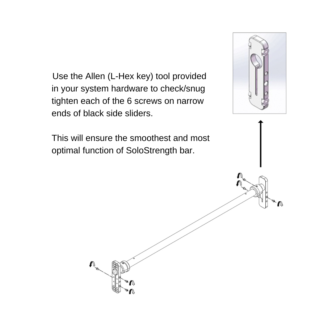
In some cases, we've noticed that during shipping the main SoloStrength bar slider screws can loosen and we suggest to check and "snug" tighten these 6 screws (3 on left and right) on side sliders of main SoloStrength bar per diagram attached.
Make sure pulling back the orange flanges, the locking pins easily pull back and retract fully with the spring loaded force. The safety lines will show when the pins are released displaying the green safety line next to the flange towards inner section of bar, indicating the pins are secure and it's safe to apply weight to the bar.
Be assured that your SoloStrength® system, once properly installed, will run very smoothly and secure safely in each height for use.
Anomalies in building doors and walls, may require some fine-tuning and adjustments to achieve desired results but the process is shortcut below in tips for each install.
We guarantee your system will work 100% smoothly and support you to resolve any challenges you may have.
PROUD TO HAVE OVER 99% CUSTOMER ASSEMBLY EXPERIENCE REQUIRING NO ADDITIONAL SUPPORT 🏅
If you get stuck and do not find quick solutions within the guidance notes/troubleshooting sections below, please feel free to reach out to our customer service. You can ask questions, chat, or share photos via email, or request a call back time for help if outside business hours. We are here and happy to help, and appreciate all the feedback to help us continually improve!
The SoloStrength System is extremely safe to use when the simple operation guidance is followed.
-
Only apply weight to the bar when the orange flanges are released fully, exposing the green line indicators next to the flange (inner side of bar) showing the pins safely in place.
-
As with any safety item, it's good practice to apply some quick pressure to the bar in an "up down" movement to test the bar is secure and locked in, as well as visual cues for the safety lines. This becomes a basic and simple habit when using SoloStrength quickly once learned.
Assembly Instruction & Video
Choose product selection below for Assembly PDF Manuals, notes, and updates to print instructions to go with relevant videos included in each section.
Download Manuals & Specifications:
-
Step1: View/Download: Main System Assembly Instructions
-
Step 2: View/Download: Base Assembly Instructions (updated notes)
-
Specifications can be be found on product page here.
-
Tip: Build one item at a time to not confuse parts/components
-
Do you have 3" or more ceiling height over the finished height of your system? (Yes? Follow standard assembly instructions below). If no, BUT you have the minimum required 2" over finished height (ie. 88" for shorter system and 92" for standard system), then you will need to follow a slightly modified assembly approach. This requires the final step of connecting the upright to the base, with the base tipped forward, connecting the uprights, then pulling the system back upwards which reduces the total ceiling height requirements to assemble your system to only +2" over the finished height.
It will be helpful to please watch video through and read instructions before starting. Most assembly questions come from overlooking the notes and details offered through instructions.
SPECIAL NOTES:
-
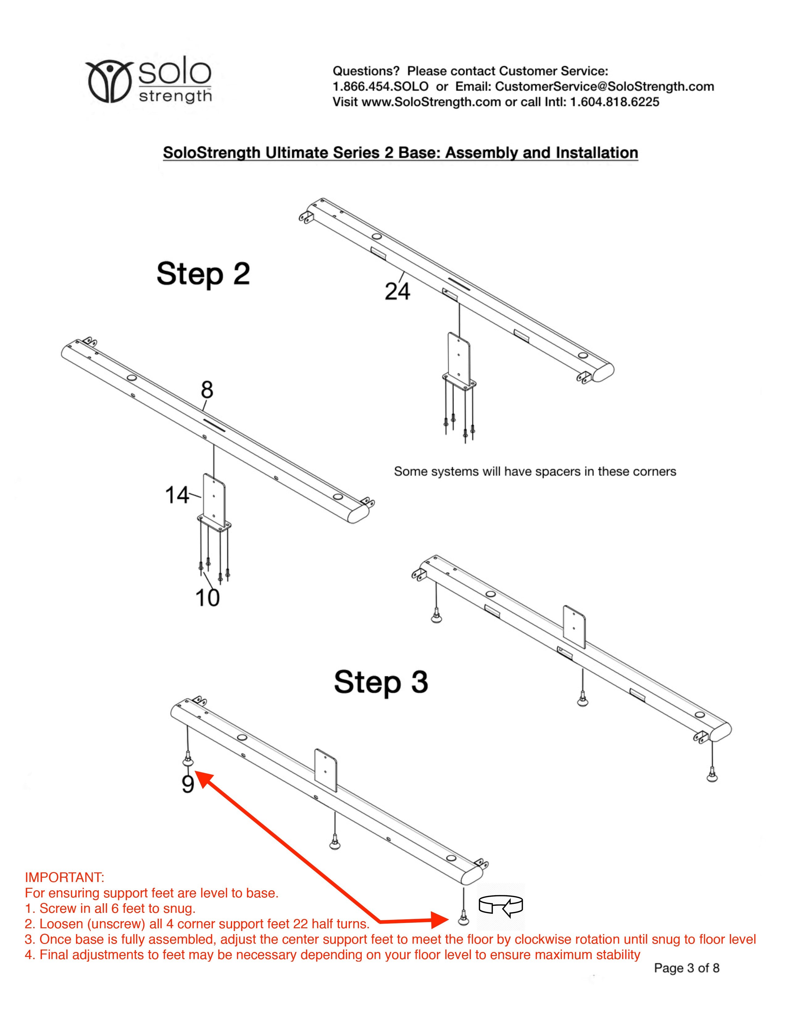
Please check freestanding base items parts # 19 and #20. There have been a few instances where labelling on parts was incorrect. For easy reference, there are 3 slats that connect the side tubes. 2 are longer (those should be labelled #19), and the shorter one (part #20) fits in the center middle section. If the part# labels is incorrect, please reference the shorter of the 3 slats as part #20, and the other 2 longer ones as #19 to avoid confusion.
-
Page 3 on Freestanding base assembly updated instructions above, has a helpful notes that are not included in print documents please view here.
-
Video does not show optional extra support board for base (showing on print and pdf instructions)
-
Step 1 is the building the main upright, first add the upper extrusions (parts 5C and 5D) to the header, then add the cover to header for easiest build. If you are adding the height extension is fits directly below the header.
-
Build the Main system upright first and set aside.
-
There will be extra parts from the Main system construction (the Main system comes with doorway mount hardware needed for wall/corner mounting also included).
-
Securing base to floor. This option is available for those wanting to secure the Freestanding system to the floor (more commonly used in commercial applications), and is accomplished by using appropriate mounting screws/washer sizes for floor surface, fit through the 4 hidden mounting holes on corners of side tubes.
-
IF INSTALLING BY YOURSELF: It can be helpful on the final step when fitting the uprights over the base connection plates, to have a second set of hands to help guide the uprights into place. However if you are assembling this stage on your own, it can improve the ease of mounting the upright if you set the support bar about 3/4 way to top header to hold onto and lift the top section over the base connection sleeves more easily.
-
*Applying the LUBE: Once the bar is installed into the channel, you should be able to run it up to around 3/4 height of system in order to lift upright and place it for assembly. Once frame is secure on base add a small amount (several drops inside channel on each corner on top of black sliders) is needed and helps to eliminate any resistance of bar movement or stick from not lifting the bar level through the channels. If alignment is off on mounting at all, you may need to refine the alignment slightly. It is recommended to apply 3-5 drops of the lubrication provided into each corner with the bar just below midway section, and run the bar up through the section and back down a dozen times. If it feels like any resistance at all, you can set the bar about 1/4 height and add drops on top of black slider corners there and run it up and down again. Same with it at 3/4 Height. This will ensure the channel is well lubricated for smoothest operation.
-
When installed and aligned correctly, the SoloStrength main bar will run very smoothly and cleanly lock into place in each height. If there is any resistance due to misalignment, It may require slightly loosening the screws to ensure alignment is square and properly balanced and aligned before tightening again.
-
Important: When setting the bar height before applying weight to the bar, quickly check for the green safety line on bar next to the orange pull flange, indicating the pin is released and locked into place, secure and safe. It is good practice to quickly apply an "up down" pressure on the bar with your hand to test as well. Only put weight on the bar when the pins are securely locked in place.
We are here to support your Success with SoloStrength!
If questions arise, check troubleshooting section below, and if not addressed please contact support.
Download Manuals & Specifications:
-
View/Download: Main System Doorway Assembly Instructions
-
Specifications can be be found on product page here.
It will be helpful to please watch video through and read instructions before starting. Most assembly questions come from overlooking the notes and details offered through instructions.
If you have a wider (30-36") door frame and a tighter corner wall section next to doorway (3-5") you can select the 3 shorter mounting brackets (part #14). You can adjust the centering of the system around the doorframe as needed to fit if tight space.
Steps:
-
Begin with first connecting one of the middle brackets to the door frame, with the screws provided. Install single screw into bracket to allow for refinement in alignment as squaring the fit to the remaining brackets. An electric drill is suggested for best results and use strong pressure.
-
Once one of the brackets is installed, tighten the nut that connects the doorway bracket to the ULTIMATE system. Following this, fit the rest of the doorway connection brackets to the frame, best as possible. They may need slight adjustments before mounting them to the frame and tightening the bolts.
-
Before connecting the second MIDDLE bracket to the door frame, gently pull in the flanges releasing the pins on the slider bar assembly, and run the bar up and down the height of the system several times to ensure its operating smoothly and spacing the system out to correct level. After it’s smoothly running up and down the system, lock the bar around center height of the frame, to assist in the correct spacing for the bracket. Use the screws to mount the second middle height bracket now and tighten a bit more, the acorn nut on this second side.
-
Run the bar up and down the height of the system again several times to help find the correct spacing and adjustments for your specific door frame. Once this is complete, raise the bar to the top level, and lock it in place. Mount one of the brackets with the screws to the door frame, and tighten the connection. AFTER this is completed run the bar the height again, make sure the bar is locking into place at various heights smoothly, and without having to adjust the FRAME at all, but this is the time to make those adjustments if needed. – Once you are happy with how the bar is locking into place, leave the bar locked in the upper locations, and secure the second bracket.
-
Slide the bar again the full height several times checking the ease of sliding, and proper locking of the pins at all holes (the line around the bar will show inside the pull flange when it’s fully locked into place securely). Focus now on the lower level connections now ensuring smooth function and proper locking into place.
-
After all mounts have been secured, ensure all doorway to frame connection bolts are tightened fully.
-
Once all screws are in place, check sliding of the Support Bar from top to bottom. Apply enough lubrication to ensure the slider is running perfectly smoothly.
Finishing:
-
*Applying the LUBE: Once the bar is installed into the channel, you should be able to run it up to around 3/4 height of system in order to lift upright and place it for assembly. Once frame is secure add a small amount (several drops inside channel on each corner on top of black sliders) is needed and helps to eliminate any resistance of bar movement or stick from not lifting the bar level through the channels. If alignment is off on mounting at all, you may need to refine the alignment slightly. It is recommended to apply 3-5 drops of the lubrication provided into each corner with the bar just below midway section, and run the bar up through the section and back down a dozen times. If it feels like any resistance at all, you can set the bar about 1/4 height and add drops on top of black slider corners there and run it up and down again. Same with it at 3/4 Height. This will ensure the channel is well lubricated for smoothest operation.
-
When installed and aligned correctly, the SoloStrength main bar will run very smoothly and cleanly lock into place in each height. If there is any resistance due to misalignment, It may require slightly loosening the screws to ensure alignment is square and properly balanced and aligned before tightening again.
-
Important: When setting the bar height before applying weight to the bar, quickly check for the green safety line on bar next to the orange pull flange, indicating the pin is released and locked into place, secure and safe. It is good practice to quickly apply an "up down" pressure on the bar with your hand to test as well. Only put weight on the bar when the pins are securely locked in place.
We are here to support your Success with SoloStrength!
If questions arise, check troubleshooting section below, and if not addressed please contact support.
Download Manuals & Specifications:
-
View/Download: Corner Mounted Assembly Instructions
-
Specifications can be be found on product page here.
-
Must view video for instructions on the corner mount bracket details
It will be helpful to please watch video through and read instructions before starting. Most assembly questions come from overlooking the notes and details offered through instructions.
Note the completion step in print instructions, where the L Brackets for doorway mount are replaced with the corner mount brackets.
-
Although not required for main SpeedFit Workout Programs, securing the wall mounts to Ledger Board Bracing and wall studs will maximize strength and ability to withstand greater lateral forces if desired (for use with bands, TRX etc).
-
If choosing to use ledger boards in the form of wood slats, suggested sizes 1/2-1" thick and 4' x80" (or larger as desired/needed to secure studs) x2 boards, secured to wall studs then attaching mounting brackets to these.
Steps:
-
Begin with first connecting one of the middle brackets with the screws provided. Install single screw into bracket to allow for refinement in alignment as squaring the fit to the remaining brackets. An electric drill is suggested for best results and use strong pressure.
-
Once one of the brackets is installed, tighten the nut that connects the doorway bracket to the ULTIMATE system. Following this, fit the rest of the doorway connection brackets to the frame, best as possible. They may need slight adjustments before mounting them to the frame and tightening the bolts.
-
Before connecting the second MIDDLE bracket to the wall, gently pull in the flanges releasing the pins on the slider bar assembly, and run the bar up and down the height of the system several times to ensure its operating smoothly and spacing the system out to correct level. After it’s smoothly running up and down the system, lock the bar around center height of the frame, to assist in the correct spacing for the bracket. Use the screws to mount the second middle height bracket now and tighten a bit more, the acorn nut on this second side.
-
Run the bar up and down the height of the system again several times to help find the correct spacing and adjustments for your specific door frame. Once this is complete, raise the bar to the top level, and lock it in place. Mount one of the brackets with the screws to the wall (or ledger board), and tighten the connection. AFTER this is completed run the bar the height again, make sure the bar is locking into place at various heights smoothly, and without having to adjust the FRAME at all, but this is the time to make those adjustments if needed. – Once you are happy with how the bar is locking into place, leave the bar locked in the upper locations, and secure the second bracket.
-
Slide the bar again the full height several times checking the ease of sliding, and proper locking of the pins at all holes (the line around the bar will show inside the pull flange when it’s fully locked into place securely). Focus now on the lower level connections now ensuring smooth function and proper locking into place.
-
After all mounts have been secured, ensure all corner mount screws to frame L Bracket connection bolts are tightened fully.
-
Once all screws are in place, check sliding of the Support Bar from top to bottom. Apply enough lubrication to ensure the slider is running perfectly smoothly.
Finishing:
-
*Applying the LUBE: Once the bar is installed into the channel, you should be able to run it up to around 3/4 height of system in order to lift upright and place it for assembly. Once frame is secure, add a small amount (several drops inside channel on each corner on top of black sliders) is needed and helps to eliminate any resistance of bar movement or stick from not lifting the bar level through the channels. If alignment is off on mounting at all, you may need to refine the alignment slightly. It is recommended to apply 3-5 drops of the lubrication provided into each corner with the bar just below midway section, and run the bar up through the section and back down a dozen times. If it feels like any resistance at all, you can set the bar about 1/4 height and add drops on top of black slider corners there and run it up and down again. Same with it at 3/4 Height. This will ensure the channel is well lubricated for smoothest operation.
-
When installed and aligned correctly, the SoloStrength main bar will run very smoothly and cleanly lock into place in each height. If there is any resistance due to misalignment, It may require slightly loosening the screws to ensure alignment is square and properly balanced and aligned before tightening again.
-
Important: When setting the bar height before applying weight to the bar, quickly check for the green safety line on bar next to the orange pull flange, indicating the pin is released and locked into place, secure and safe. It is good practice to quickly apply an "up down" pressure on the bar with your hand to test as well. Only put weight on the bar when the pins are securely locked in place.
We are here to support your Success with SoloStrength!
If questions arise, check troubleshooting section below, and if not addressed please contact support.
Download Manuals & Specifications:
-
Step 1: View/Download: Main System Assembly Instructions
-
Step 2: View/Download: Wall Mounting Kit Assembly Instructions
-
Specifications can be be found on product page here.
It will be helpful to please watch video through and read instructions before starting. Most assembly questions come from overlooking the notes and details offered through instructions.
For Maximum Secure Install:
-
Although not required for main SpeedFit Workout Programs, securing the wall mounts to Ledger Board Bracing and wall studs will maximize strength and ability to withstand greater lateral forces if desired (for use with bands, TRX etc).
-
If intentions are to use for SpeedFit Training suggestions only, primarily vertical forces, and lighter lateral (outward) forces, you can secure with anchor bolts/drywall plugs safely, ideally with one section connecting into stud as fitted in your space. The Ledger Board option offers most flexibility on location with maximum secure install.
-
If choosing to use ledger boards in the form of wood slats, suggested sizes 1/2-1" thick and 4' x44" (or larger as desired) x3 boards, secured to wall studs then attaching mounting brackets to these.
Steps:
-
Follow the steps to notice completion point for main assembly, then switch to wall mount kit. Add the wall mount installation arms onto the mounting brackets and tighten them firmly before marking wall to secure the screws.
-
Start with the middle height brackets and lightly tighten the screws – ensuring the system is properly spaced before tightening the second side. You do this by running the slider bar up and down the height of the system before securing to wall.
-
Next space the system again by running the bar up and down and doing the right side upper section and then right side lower section before doing the left side upper and lower wall mounts.
-
Keeping in mind the 6 anchor points, the system is well braced with drywall or concrete anchors provided, for suggested use. If you are anticipating extremely heavy lateral forces and want to make sure your system is secured to studs, you can secure the 6 anchor points to a sheet of plywood (Dimensions: 48” x 76”) and then securing that to the studs where they are located behind it. This also gives you a roughly 30” wide space for securing a mirror too if desired.
-
The Ledger board options work equally well with 3 boards in dimensions in notes above.
-
For reference on how to use anchor screws for different wall surfaces view wiki page here.
Finishing:
-
*Applying the LUBE: Once the bar is installed into the channel, you should be able to run it up to around 3/4 height of system in order to lift upright and place it for assembly. Add a small amount (several drops inside channel on each corner on top of black sliders) is needed and helps to eliminate any resistance of bar movement or stick from not lifting the bar level through the channels. If alignment is off on mounting at all, you may need to refine the alignment slightly. It is recommended to apply 3-5 drops of the lubrication provided into each corner with the bar just below midway section, and run the bar up through the section and back down a dozen times. If it feels like any resistance at all, you can set the bar about 1/4 height and add drops on top of black slider corners there and run it up and down again. Same with it at 3/4 Height. This will ensure the channel is well lubricated for smoothest operation.
-
When installed and aligned correctly, the SoloStrength main bar will run very smoothly and cleanly lock into place in each height. If there is any resistance due to misalignment, It may require slightly loosening the screws to ensure alignment is square and properly balanced and aligned before tightening again.
-
Important: When setting the bar height before applying weight to the bar, quickly check for the green safety line on bar next to the orange pull flange, indicating the pin is released and locked into place, secure and safe. It is good practice to quickly apply an "up down" pressure on the bar with your hand to test as well. Only put weight on the bar when the pins are securely locked in place.
We are here to support your Success with SoloStrength!
If questions arise, check troubleshooting section below, and if not addressed please contact support.
Download Manuals & Specifications:
-
View/Download: Full Foldup System Assembly Instructions
-
View/Download: Foldup System CONVERSION KIT Assembly Instructions
-
Specifications can be be found on product page here.
-
*Applying the LUBE: Once the bar is installed into the channel, you should be able to run it up to around 3/4 height of system in order to lift upright and place it for assembly. Add a small amount (several drops inside channel on each corner on top of black sliders) is needed and helps to eliminate any resistance of bar movement or stick from not lifting the bar level through the channels. If alignment is off on mounting at all, you may need to refine the alignment slightly. It is recommended to apply 3-5 drops of the lubrication provided into each corner with the bar just below midway section, and run the bar up through the section and back down a dozen times. If it feels like any resistance at all, you can set the bar about 1/4 height and add drops on top of black slider corners there and run it up and down again. Same with it at 3/4 Height. This will ensure the channel is well lubricated for smoothest operation.
-
When installed and aligned correctly, the SoloStrength main bar will run very smoothly and cleanly lock into place in each height. If there is any resistance due to misalignment, It may require slightly loosening the screws to ensure alignment is square and properly balanced and aligned before tightening again.
-
Important: When setting the bar height before applying weight to the bar, quickly check for the green safety line on bar next to the orange pull flange, indicating the pin is released and locked into place, secure and safe. It is good practice to quickly apply an "up down" pressure on the bar with your hand to test as well. Only put weight on the bar when the pins are securely locked in place.
We are here to support your Success with SoloStrength!
If questions arise, check troubleshooting section below, and if not addressed please contact support.
*Video reference below is to assist for main upright component. The wall mounting fold-up hardware instructions included above detail the connection assembly for that step.
Download Manuals & Specifications:
-
View/Download: Dip/Row Bar Assembly Instructions
-
View/Download: Wide Grip Bar Assembly Instructions
-
Specifications can be be found on product page here.
It will be helpful to please watch video through and read instructions before starting. Most assembly questions come from overlooking the notes and details offered through instructions.
Please note the instructions to avoid tightening the screws before connecting all parts/screws in place, then complete by tightening. The assembly fit is precise and by keeping the screws slightly loose while connecting all parts will allow the movement to align all parts.
Wide Grip Pull Up Bar follows similar assembly reference to the Ultimate Dip and Row Bar video below.
We are here to support your Success with SoloStrength!
If questions arise, check troubleshooting section below, and if not addressed please contact support.
More information on Ultimate J-Cups here.
A pair of C-Clips are included with the freestanding base. If you have other install options, and you wish to mount your clips/bar to the wall for clean storage, you can purchase C-Clips here.
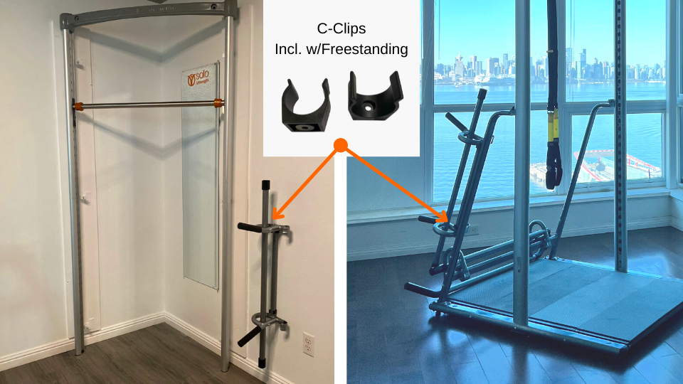
Built in slide on secure attachment for side of Rear Support Bar (Freestanding Model Option).
Option to secure directly to wall/studs for clean bar storage.
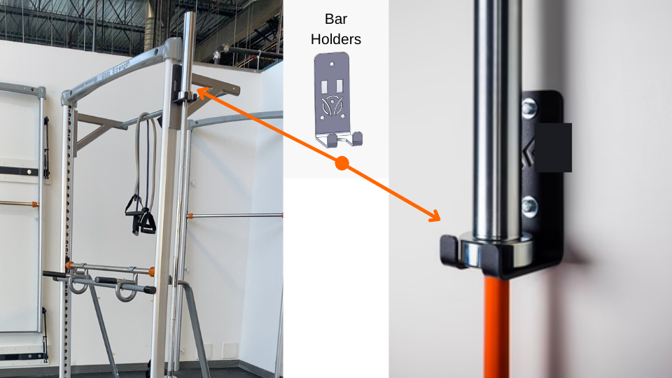
*For older design Rear Support Bars without the built in anchor points, you can easily attach the Bar Holders securely to flat side of accessory, with heavy duty double sided tape works perfectly for clean safe adhesive.
Download Manuals & Specifications:
-
View/Download: Height Extension Assembly Instructions
-
Specifications can be be found on product page here.
*Height extension fits directly under the header.
We are here to support your Success with SoloStrength!
If questions arise, check troubleshooting section below, and if not addressed please contact support.
QUESTIONS?
DON'T WORRY WE'VE GOT YOU COVERED!
Most questions or troubleshooting can be found in the below information. If not please contact us for support, or use chat and we will find for you the quickest support solution including setting up video with support if required to view/resolve your questions efficiently.
Troubleshooting & Tips
SoloStrength® ULTIMATE systems are precision built. If you have any difficulties during assembly please reference below or contact our support team. We are happy to help get you get assembled and started quickly on your SoloStrength SpeedFit Training!
If you find any difficulty with the main bar sliding up and down smoothly:
-
Ensure there is sufficient lubrication in the inside channel.
-
Ensure the side screws of sliders are snug (reference "before you begin" above)
For wall/doorway/corner mount options, you may have tightened alignment slightly off square:
-
Loosen the 6 points of contact to find easy sliding before resetting the anchor positions. *Reference video.
For Freestanding Systems:
-
If there is any alignment challenges, loosen the midway contact support point (connection from the base to the uprights) and realign the midway support arm screws (part 22) to ensure they are square.
If you find screws are coming loose over time, we suggest using loctite (or similar product) on each screw to keep it in place (but still allow to release if needed).
It's good practice once a month when doing basic wipe down and cleaning, to quickly check and test screws for snugness. There can be many ranges of forces on the system which may eventually loosen the screws/bolts and this can cause slight squeaks or tiny movement in system as a result. Keep screws tight for optimal function.
For higher volume use you may find you need to check screws more frequently, or as suggested for commercial use to add small drop of loctite to the screws (particularly inside main channels of uprights that endure the most cross forces) to eliminate need to check.
On Freestanding system, if base cover boards are not snug they may begin to have a squeaks due to movement which is quickly resolved by tightening floor boards.
If your Freestanding Base feels like it has a teeter totter effect, it's due to the middle support feet being a high point and can easily be adjusted by ensuring the corner feet are equal or just longer than the middle support feet from base. This will ensure your base is flat to your floor (even if not level floor) and solid and stable for your SpeedFit exercising.
Start with all the support feet screwed in "finger tight" in all locations.
If your flooring is level, then you can reach under and unscrew the middle section support feet to reach the flooring surface just touching surface is perfect. These are for added flex support to entire system and stability.
If your flooring is not level in the location you wish to place your system (this is not a problem :)), you will know this by the base not feeling very secure and sitting flat and firm on the surface. It will feel like it is rocking. In order to use the purpose designed adjustable support feet to stabilize the base on this surface, you will need to adjust the corner support feet by unscrewing them in the locations that feel they aren't touching the floor, then follow the step above for middle support feet.
The Ultimate Dip Bar is a simple assembly however you must pay attention to not tighten the screws in any step until all screws are in place started, and handles are balanced.
Once all screws are in place you can complete assembly by tightening to finish.
Maintenance
SoloStrength ULTIMATE systems require exceptionally little maintenance. Details can be found in the user manual provided, with a summary below:
-
Use paper towel or cloth along the inner extrusion channels to clean the dust which can collect, and re-lubricate as required (monthly or bi-monthly is more than adequate for this).
-
For Freestanding base foam and all components, you can wipe clean your system with light detergent solution and warm water as required, and it’s recommended to towel down after each use for keeping most hygienic. You can use anti-bacterial wipes on contact surfaces such as the main SoloStrength bar, flanges and uprights to keep fresh.
-
CHECK SCREWS regularly to ensure they haven’t loosened. Indicators of loosened screws is subtle squeaks in system during use as movement from the screws needing tightening is allowed. Floor boards on base of freestanding and rear lower connection bar, as well as inner channels screws in uprights are the most likely to need attention if in high volume use. If you find screws are becoming loose through your use, we suggest using loctite (or similar) product to hold them tight.
-
Ensure proper functionality of the Support Bar spring loaded pins that they easily move inwards and lock fully outwards to display the PIN LOCKED Green line indicator on the bar when properly locked out.
-
To clean the aluminum frame uprights if any inside channel lubrication fluid is spread, the same detergent solution can be used as above, or a window or glass cleaning (Windex type) solution to keep your system looking and functioning like new. * We've found a little cleaning hack that works great is to add a sprinkle of baking soda to toothpaste, apply to a cloth/towel and gently rub the area clean and wash off to perfectly clean as new look.
Moving SoloStrength
Moving your Freestanding Ultimate system is super simple!
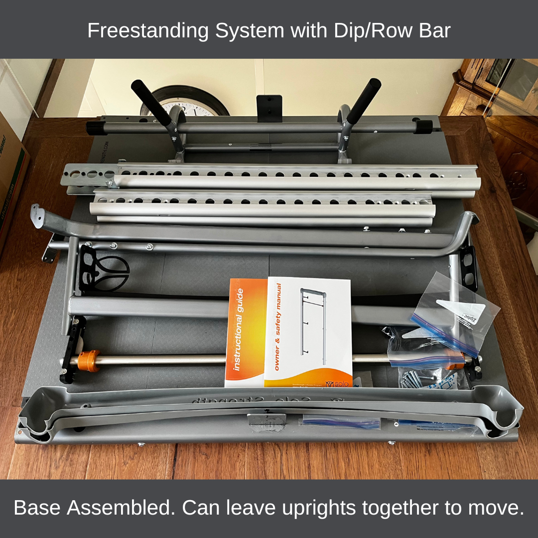
You can reduce the system for easy transport into 4 easy manage components comprising of the main upright, the base flat, two piece for midway support arms. Reference assembly details above and reverse the last 3 steps.
-
Disconnect the midway connection screws holding the main upright to the midway support arms
-
Remove the 8 screws holding the midway support ams to the base
-
Remove the 2 screws (each side) holding main upright to base
This results in 3 pieces and roughly 5 minutes to disassemble and reassemble again after moving!
Reverse the last mounting step in assembly instructions above.
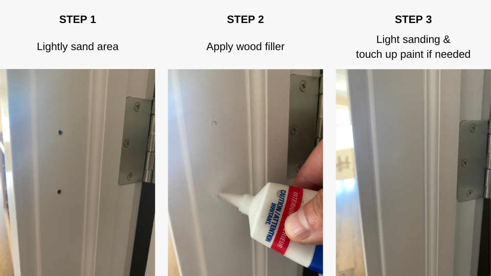
The screw holes in doorway frame or wall, can be easily filled with wall or wood putty (depending on your surface) and found at any hardware store. See hole repair example below. Simple google search for drywall screw hole repair offers other options.
Smooth out the putty once applied with light sanding and the holes disappear!
<=== Install, remove when moving, 5 minute patch and go!
Many people don't realize how easy and simple it is to patch small screw holes in wood or drywall. The process takes 5 minutes and materials less than $10.00.
Google search "wood screw hole repair" or "drywall screw hole repair" for reference and other options. There are fillers for full range of colors and natural wood color matching for simplicity.
It takes very little time to erase any presence of your SoloStrength installation so you can move it to another location without any trace. ✅
Customer Submission Reference

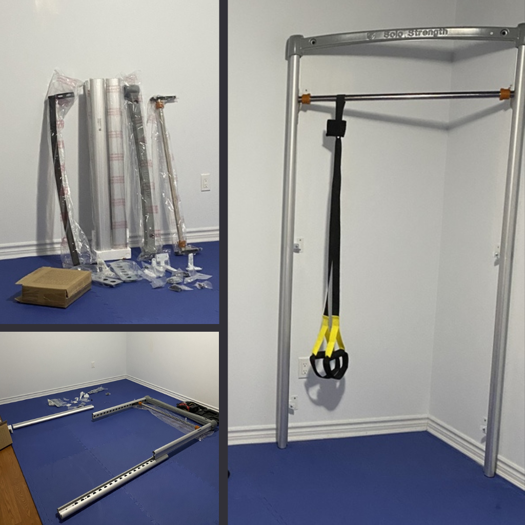
1000s of Customers Worldwide easily install their SoloStrength and we've refined our notes from generous and helpful feedback along the way.
We care about your success and best experience from shopping SoloStrength, through shipping/assembly and training.
Together we make it better. Thank you for your business and we appreciate any feedback you would like to share with us if you feel it will help us improve our communication or guidance. You can submit photos/videos directly to our secure cloud here.
Contact us with any text suggestions here.
Gratitude and thanks. 🙏


